

ASME B30.20-BTH-1: Lifting Beams
ASME B30.20 & BTH-1: Lifting Beam Design
Below-the-hook lifting devices such as spreader bars and lifting beams must be designed in accordance with ASME BTH-1 and are to be manufactured and used in accordance with requirements of ASME B30.20 which specifies requirements for marking, inspection, construction and operation. The design of lifting beams must meet specific calculation requirements per BTH-1 to verify that the design will be safe and effective for its intended below-the-hook lifting application. By using BTH-1 for designing lifting beams, the different failure modes of the beam will be addressed, and appropriate safety factors will be applied to the design, dependent on the intended use or classification of the beam.
Lifting Device Configuration
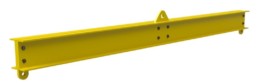
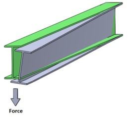
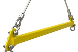
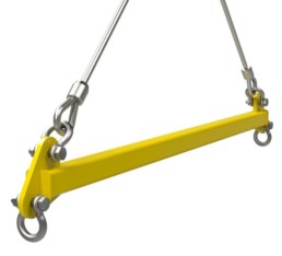
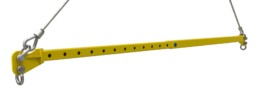
The first step in developing a lifting device is to determine the lifting configuration, max lift capacity and max spread (width) that is desired. In this article, we will discuss designing a lifting beam according to ASME BTH-1. Therefore, we are looking at a beam that is lifted from the centre and loaded at the ends. This type of lift subjects the beam to flexure (bending) and shear, with bending stress and lateral torsional buckling being the primary modes of failure.
Classification
After establishing the style and capacity required of the lifting beam, the Design Category and Service Class must be confirmed, according to ASME BTH-1. The design category and service class establish the requirements for safety factor for strength and fatigue that will be used in the remainder of the design calculations for the lifting device. The design category and service class are discussed in more detail in the article: Introduction to Below the Hook Design
Structural Design
ASME BTH-1 specifies design calculations for different types of loading of a lifting device including tension, compression, flexure, shear and combined loading of beams. For lifting beams that are subject to flexure, ASME BTH-1 has calculations that define the maximum allowable bending stress based on beam geometry, material properties, and lateral bracing spacing (the distance between braces that resist lateral displacement of the compression flange or twisting of the beam cross-section). Typically lifting beams do not have bracing to resist either of these movements (a single symmetric cantilever beam with no external bracing to stabilize the beam), therefore the lateral bracing spacing is defined as the distance between the outermost lift points of the lifting beam.
Based on the BTH-1 calculations, if the beam length is short enough the beam yield strength limits the lift capacity of the beam, but if the beam length is over the lateral bracing spacing requirement (per calculations in BTH-1), the buckling strength of the structural member defines the allowable lift capacity of the beam, resulting in a reduced maximum allowable bending stress.
Depending on the features of the lifting beam, additional calculations for connections (bolts, pins and welds) are specified to determine suitable sizing and spacing of each.
Calculations for fatigue are also specified in the standard, dependent on the service class of the bar and bar geometry.
Example: Capacity Reduction of Lifting Beam vs Length
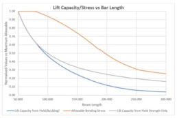
The following chart shows a comparison of a W-Beam lifting beam with lifting capacity based on simple bending stress calculations vs calculations that account for buckling per ASME BTH-1. It shows how there is a reduction in lifting capacity in longer beams due to the instability from lateral torsional buckling.
Allowable bending stress vs beam length per BTH-1 calculations (Orange Plot)
According to BTH-1 calculations, the short beam can be loaded to full yield strength (accounting for safety factors), but as the beam length (or lifting spread) increases, the stress reaches an inflection point where the allowable bending stress starts to drop off. It is at this point where the beam buckling takes over as the limiting factor for load capacity. There are two other inflection points in the curve, one at a beam length of about 180 and another at a beam length of 255. These points are where calculations switch according to BTH-1, due to the beam length (There are several different calculations for allowable stress which are dependent on the beam properties and beam length, with different calculations for different lengths of beams).
Lift capacity vs beam length per BTH-1 calculations (Blue Plot)
The lift capacity of the beam is calculated based on the allowable stress (Orange Plot) and beam length. The calculation includes the weight of the beam.
Lift capacity vs beam length based only on bar yield strength (Gray Plot)
The allowable bending stress is a product of calculations from BTH-1, and the lift capacity is calculated from the allowable bending stress. The bending calculations include bar weight, but do not account for shear stresses. As well, as a comparison, the gray line represents the calculated beam lift capacity based on only bending strength, without accounting for buckling effects.
As can be see from the allowable stress plot, the short beam is permitted to achieve full bending stress (with safety factors), but at a certain point, the allowable bending stress is reduced, to account for the buckling strength of the beam.
Hey, you made it to the end! Congratulations! I hope this article makes you wonder if the engineers you are currently using are just tossing their lifting beam designs into solidworks and applying loads rather than doing the full calculations required by the code. If you are ready to skip the stress of designing your own lifting equipment take a second to check out our store: Basepoing Engineering Store Where you can find fully engineered stamped and certified drawings based on years of experience designing and building spreader bars.

ASME B30.20 & BTH-1: Introduction to Below the Hook Design
An Overview of ASME BTH-1 (spreader bars and lifting beams)
When planning to design lifting beams (or any other below-the-hook lifting devices), there are many aspects that must be considered beyond finding materials that meets a few basic engineering calculations. Along with stress, buckling is also a critical factor in lifting beams that must be addressed in detail to ensure that the structure can handling the loads imposed on it. ASME BTH-1 clearly defines rules for material selection and determining what kind of load would be permitted by the design in question. Following the procedures outlined in BTH-1, you can successfully design a below-the-hook lifting device that will handle the loads imposed on it.
What is ASME BTH-1
ASME BTH-1 “Design of Below-the-Hook Lifting Devices” is an ASME design standard and is to be used in conjunction with ASME B30.20, the ASME safety standard for Below-the-Hook Lifting Devices.
ASME B30.20 defines the safety requirements for below-the-hook lifting devices including marking, inspection, construction and operation, whereas ASME BTH-1 defines the design requirements for developing these lifting devices. BTH-1 addresses design requirements including:
- classification of the lifting device based on frequency and capacity of lifts,
- structural design requirements related to member design, connection design (pins, bolts, welds), and fatigue,
- mechanical design requirements for the mechanical components (sheaves, wire rope, gears, bearings, shafts, fasteners),
- electrical component requirements for electrical components used to operate below-the-hook lifting devices,
- lifting magnet design requirements.
While BTH-1 is broad in its coverage of design requirements for below-the-hook lifting devices, only portions of the design standard are applicable to spreader bars and lifting beams, in particular beam classification and the structural design requirements. These items are discussed in more detail below.
Classification of Spreader Bars and Lifting Beams
Spreader bars, lifting beams, and other below-the-hook lifting devices are classified based on the frequency and capacity of lifts that are required of the device. In the latest revision of BTH-1 (2017), there are three design categories, categories A, B and C, as well as five different services classes, service class 0 through 5. Together the design category and the service class define the design requirements of the beam related to material strength and fatigue.
The design category establishes the different stress factors to be used in beam design:
- Category A lifters are designated when the magnitude and variation of load is predictable, and require a design factor of 2 on yield/buckling
- Category B lifters are designed for unpredictable lift scenarios where the magnitude of lift can vary significantly and require a design factor of 3 on yield/buckling. This is the most common design category and is what Basepoint Engineering lifting beams and spreader bars are typically designed for.
- Category C lifters are designated for special-application lifting devices where a specified design factor is required and require a design factor of 6 on yield/buckling.
Service Class
The service class designates the number of load cycles, or fatigue life for which a beam is designed. Basepoint Engineering lifting beams and spreader bars are typically designed as Service Class 0, which is for 0-20,000 load cycles, although beams with different service classes can be designed on request. Service Classes 1 through 5 cover load cycles from 20,001 through 2 million load cycles.
Structural Design
ASME BTH-1 specifies design calculations for different types of loading of a lifting device including tension, compression, flexure, shear and combined loading of beams. Depending on the style of lifting device, only certain structural design considerations apply to a specific device. For example, a lifting beam with a centre pick point and load suspended on the two ends of the beam are loaded in flexure, therefore compression and tension calculations aren’t specifically relevant to this device. Conversely, for a telescopic spreader bar with a centre pick point and two slings out to the ends of the spreader bar the loading on the beam would be primarily compressive, although if the ends of the spreader bar are set up such that bending is applied to the ends of the spreader bar, then a combination of load calculations must be utilized.
The structural design section of the standard also includes requirements for connection design including bolted connections (bolt quantity, allowable loading, required tightening and hole requirements), pinned connections (pin hole strength, pin clearance), and welded connections (weld size and properties).
Fatigue design is not required for bars classified as service class 0 due to the low number of total load cycles, but as the number of load cycles is increased, the potential for fatigue failure increases. BTH-1 includes a structural design section covering fatigue requirements for lifting devices classified as service classes 1 through 5.
Mechanical Design, Electrical Components and Lifting Magnets
In addition to all the information previously discussed, ASME BTH-1 also addresses design requirements for mechanical design, electrical components and lifting magnets. These sections of the standard apply to components that are loaded in below-the-hook lifting devices, and in some devices or scenarios they would be relevant. They are not discussed in this article because they do not generally apply to typical spreader bars and lifting beams.
Conclusion
This article is a brief overview of what is covered by ASME BTH-1, particularly with respect to the design of spreader bars and lifting beams. Emphasis was made to focus on the areas of BTH-1 that apply to these devices. If you are looking for more information on BTH-1, feel free to contact us, or you can wait for future articles that will discuss applying BTH-1 to design of lifting beams and spreader bars in greater detail. If you are looking to manufacture spreader bars that have been designed in accordance with requirements of ASME BTH-1, we can provide you with engineered shop drawings of designs that are ready to manufacture. They can be found at our store. If you have a unique design challenge where you could use some engineering assistance, please contact us to see how we can help you.
Expanding Spreader Bar Possibilities With Spacers
Expanding possibilities with spacers:
With all telescopic spreader bars one of the main issues is balancing strength of material with material selection that allows the two pieces to slide inside of each other nicely. Every person I have ever spoken with that has been involved in building telescopic spreader bars has built one that didn’t slide very well after paint. The following are my tactics for dealing with this issue.
Go With What Works:
Most of the spreader bars that I produce get powdercoated. There are a few reasons for this but what I can tell you, is powdercoating goes on very thick and the chances of clearances being different post paint is very real and needs to be accounted for. There is however, a tried and tested combination of tubing sizes that has worked every time for me. That is selecting an outside tube that is 0.5” larger in size than the inside tube and has a thickness of 3/16”. For instance 3×3 tubing slides inside of 3.5×3.5×3/16 really well. This combination leaves 1/16” of clearance all the way around the tube which is enough for one layer of paint (remember you don’t paint the inside of the one tube) and clearance for the weld seam.
Don’t know what a weld seam on tubing is? Check this materials article out Stocking Materials for Spreader Bars
If you can use a design that falls into this category that’s great! It is by far the most efficient combination to use. The limitations of this design are that despite having free control of the thickness of the inside tube you are stuck with a 3/16” outside tube which will have an inevitable limitation for regional buckling because of the thin wall. Check this other article out for 5 tips for getting the most out of your 3/16 tube.
Put a spacer on the inside tube:
If you are in a situation where you can’t quite get the sizes to work out one option you could have is to repad the entire length of the inside tube. The times I have done this it is generally on larger sized bars and happens for one of two reasons. The first reason to need to do this is the load on the pin requires a thickness greater than what is available in that tubing size. For instance, I don’t believe 3x3x0.5” tubing is easy to get but if you need 0.5” thickness to give enough surface area for your pin then repading the tube is your only option. The other situation that I see this happen in is when you get into the larger sized bars and the tubing starts to skip sizes. Like you can get 6” tubing but not 6.5” so you are left trying to get a 6” tube to slide into a 7” tube. Repading the whole tube is by far the most expensive option available. If you think about welding a plate down each of the 4 sides of a tube that is 30ft long you have effectively gone from the 20” of weld required to attach the end connection to a maximum of 240’ of weld. Wow.
I often see engineers that sporadically get involved in spreader bars choose this option. I believe its half because it’s an easy solution from an engineering point of view but also because you get trapped as an engineer re-running your calculations because as you repad the tube technically you could use a smaller tube to handle the buckling. If you do find yourself using this tactic I have four tips to make it easier:
- Use appropriately sized flatbar rather than plate sheet to make it easier.
- Weld the repads down the length of the tube before drilling your holes. This will ensure proper hole alignment and dramatically reduce your headaches. Remember you are probably doing this because you need more bearing surface on your holes so if they are off by 1/16” you will only engage one surface. This will also save you from the worst case scenario where you are off by half a hole – in which case you should just start over.
- Consider stitch welding the repad next to each hole and skipping the parts of the joint between the holes. If your hole centers are every 12” you could consider 4-6” of weld every 12” centered on the holes. But consult your engineer on a case by case basis.
- Split the repad that lines up with the seam into two so that it has enough clearance.
Repad the Outside Tube:
This is a fairly common solution to the problem as well. The quick and dirty way to approach this is to weld metal spacers to the inside of the larger tube close to the opening and potentially matching repads at the base of the smaller tube. This will allow you to remove any slop between the tubes by adjusting the thickness of the repad being welded in. The high-tech solution which is common on crane outriggers and booms is to have a bolt in UHMW (Teflon) slider that can install. Either of these options are great and can potentially make a nice spreader bar. Just be sure you are thinking about assembly/disassembly before you start so you don’t weld yourself into a bar that can’t come apart for service.
Use Bearings:
This is my personally favorite option of getting two tubes to slide inside each other. There aren’t very many manufacturing companies out there using this strategy which is a shame because it makes an amazing product. The idea is to design your spreader bar with tubing that works best from an engineering point of view regardless of clearance. Ideally your outside tube will be 1” larger than your inside tube. You then cut specific brackets and install roller bearings to maintain the perfect fit. You put 2-4 bearings around the outside of the larger tube and 2-4 bearings on the butt plate of the smaller tube. You have to be careful to do this in a way that allows you to disassembly the two pieces because eventually the bearings will need maintenance. The finished product is amazing and even 80ton 60ft bars can be slid open or closed with one hand. If memory serves me correct I believe the bearings I use are around $20 so it isn’t a huge cost consider how well it works.
I hope that gets your creative juices flowing and you re-think your strategies for designing and building telescopic spreader bars. All of the Heavy Spreader Bars in the Online Store come with bearings standard but if you want them on other combinations of bars please let me know. If you have questions or comments please leave them below. I also wouldn’t mind hearing from everyone that has ever built a spreader bar and messed up the clearance between the telescoping components so I know I am not alone in this.
Thanks for reading this article and hopefully we are all on the same page with how to talk about spreader bars now. I will probably update this document every time a new term comes up but for now it is what it is. If you enjoyed the article and want to receive more update from us please take a moment to sign up for our mailing list. If you are just starting your journey into manufacturing spreader bars you should read this article next: An Introduction to Stocking Materials for Spreader Bars.

Equipment Certification Customer Management Systems
Managing New Customer Contact with Software
I have always thought the money was in the follow up. When you start a new weld inspection company you spend the first couple months running around and meeting everyone letting them you exist and what you can offer. But after that initial phase how do you manage your follow up communication? Do you visit once and forget them? Visit once per year or what strategy? Let me now in the comments.
There is a large “CRM” fad in online marketing these days and I have to say I am a big fan of the software – I am just not a fan of the price. CRM stand for customer relationship management. These CRM packages generally have some sort of interface for you to enter your contacts into it and then record when you have a phone call or send an email. The idea is that all the communication is documented in one place so that any team member can participate/manage. Depending on how complicated the software is, and how tied it is into the rest of your operations there are a great deal more features that it can come with. For the basic company though I feel tracking last touch on customers is most important. Now, Im not here to sell you a CRM package, a quick google search will find you a million options with well planned out sales strategies. I’m just here to tell you that you need to do something.
Why Last Touch Means something:
We have all hear the sales myth that it takes 7-13 touches to make a sale.
- Sales force says 6-8 touches to generate a sale
- Online marketing institute says 7 – 13+
As I write this I am calling it a myth but I believe its true. The key failing point for me has always been how do you develop a system and strategy to deliver these 7 touches without forgetting, losing track or doubling up. If you are going to manage the process you need track a metric and for me balancing staying in touch with not being too annoying with your direct communication. That’s why I choose to track days since last touch.
Days Since Last Touch:
For small companies without a huge sales force I don’t think you need a complicated strategy or a bunch of metrics. All you need to have is a list of people you would like to do business with and the days since they last heard from you. This way you can scan the list and reach out to people as required. It will also let you get familiar with how to deliver your communication as time passes. Out of sheer boredom you wont want to use the same communication platform every time. So how do you track this?
It is actually a little more difficult then pen and paper or a simple excel since you technically need a two dimensional array:
Array 1: You need a list of customers & contact info .
Array 2: List of communication attempts for each customer.
Because of this two dimensional array you might find using pen and paper, spreadsheets or any other manual process a bit difficult. Here are three strategies you could use:
Using Excel:
I have tried to use excel before with some success. It takes a bit to manage and isn’t very mobile friendly but its free so that’s nice. Basically use a table feature and on excel sheet per customer. The main dashboard shows days since last contact along with link to the customer sheet. You can scan the dashboard for info then click to go to a more detail information list for each customer. Its not a great system for 100s of entries since excel isn’t design to have that many sheets. Its functional and certainly somewhere you can start. You can download a copy of what I was using here:
Paid Online Systems:
There are a bunch of options here if you are ready for pay $20-150 a month you can get some powerful software packages. I would assume that if you were ready to spend $150 a month on a CRM system you probably have a well developed sales force and need an enterprise sales package. On the high end of functionality (and price) Sales Force, Microsoft Dynamic a bit more reasonably prices sugar CRM. You can check out this page for a brief overview https://www.softwareadvice.com/ca/crm/#top-products and each page has a pretty good video to watch but they are relentless about following up and know how to sell online so be careful where you put your contact info.
What I am using now:
These days I am using Hubspot’s free CRM online software (https://www.hubspot.com/) . At previous jobs I have used the full hubspot suite and paid lots of money a month for but ironically never used their free CRM plug in. I would describe hubspot as a thought leader on modern sales techniques and have a great blog and even better software package. However, these days their free crm it’s a perfect starting point. Its quick to set up and easy to manage. There are apps you can download so you can enter information on the fly as you are working. It categorizes all contacts by customer name and company name and will even fish some information off google for you. The free version doesn’t have all the functionality of the software and it is desperately missing a decent dashboard but for the small companies you will find value in using anything rather than shopping around for a complicated software and then not using it properly. Get your feet wet here and move up when you are ready.
That’s it. I am still learning to use these tools to supercharge my sales but I like to share what I am working on and what I am thinking. I do think this is the answer to some common problems for many companies. For more reading check out this article on choosing a digital inspection program. If you like what you read here feel free to contact us. We are currently looking for Canadian inspection companies that need 3rd party engineering support. We offer competitive packages for certification services for cranes, manlift etc. Shoot me an email if you are thinking about getting into equipment certifications and need engineering support..
High Tensile Steel In Lifting Equipment
High Tensile Steel in Lifting Equipment.
If you have read much of my writing over the years you will know I love high tensile steel. It is an easy and cost effective way to increase strength and reduce weight. Over the years I have used high tensile steel on many of my lifting equipment however, I have recently changed my opinion on it. This article will cover some of the pros and cons of using exotic materials.
The two most important properties structural engineers care about is tensile strength or yield strength and elongation. One measures the internal stress that a material can resist before permanently deforming and the other is and indication of how much a material will stretch before failure. These matter because when we do our calculations we determine deflection and stresses. Sometimes an engineer will design to a minimum deflection standard such is the case with floor joists or rails for an overhead crane or strictly on yield. Often it’s a mixture of keeping deflection low enough to not change the loading direction and stresses low enough that it doesn’t break. So how does high tensile steel come into this? Well selecting a different, high tensile, material can allow us to have 2-3 times higher internal stresses capacity while the resistance to bending remains the same.
High Tensile What?
My preferred high tensile steel is QT-100 but others such as weldox or hardox also exist. What a steel mill does to make high tensile steel is put it through a process of quenching and tempering. There is a lot of science contained in this process but through this process they can manipulate yield and brittleness. www.canadianplate.com describes QT-100 as follows:
Quench and Tempered Steel is heat-treated to develop yield strength. This is a cost effective choice for applications which require high strength, improved notch toughness, superior weldability and good forming ability, as well as good resistance to brittle fracture and is suitable for structures where notch toughness at low temperatures are a design requirement. This meets specific strength and Charpy V-notch requirements.
Why I love High Tensile Steel:
So to start with why I love using high tensile steel:
- It is often similarly priced to mild steel
- It has a yield 2-3 times higher than standard structural steel so we can try and make our projects 2-3 times lighter.
- Depending on material specifications it can bend as much as mild steel but doesn’t break until much higher loads. This is a built in safety factor as people will “see” that something is wrong before it fails catastrophically.
- Qt100 has GREAT low temperature performance.
So what’s not to love?
Why high tensile steel doesn’t belong in basic lifting equipment:
The biggest issue I have with using high tensile steel on lifting equipment is that it isn’t very common. When lifting equipment gets inspected it is common that the original engineered drawings aren’t readily available so inspectors like to make assumptions. It is standard practice to repair any faults or cracks with mild steel procedures. This means people are repairing cracked welds with 7018 wire with a tensile strength of 70kpsi where the material could have a yield of 100kpsi or higher. Depending on how high the stress is this 30ksi difference in yield might not be a problem or it might cause a catastrophic failure you just don’t know without reviewing it.
The other reason I suggest caution when using high tensile steel with lifting equipment is specifically with the lug and shackle interaction. The most common place to try and use a higher tensile steel is on the end lugs of a spreader bar. This sounds like a good idea except all the shackles are sized to go through mild steel.
For instance if you look at this Crosby info sheet (borrowed without permission from https://www.thecrosbygroup.com/catalog/shackles/crosby-213-carbon-round-pin-anchor-shackles/)
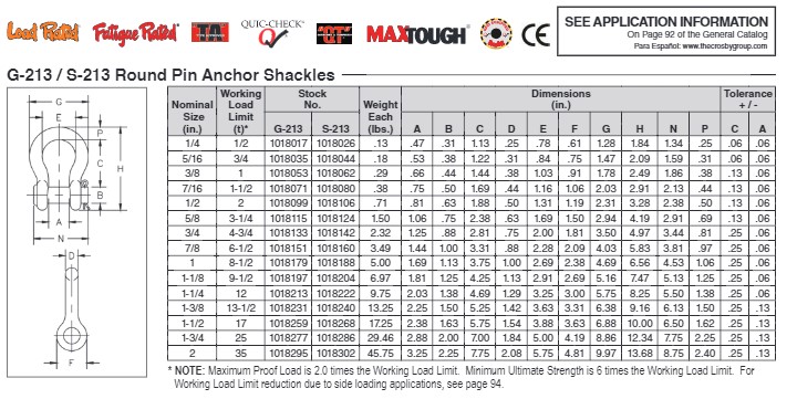
Crosby's 35t shackle has a 3.25” throat opening. If our lug comes out as needing to be 3” mild steel but we are clever and try to use QT-100 and reduce the thickness of that lug to something around 1.5” (I’m just using this as an example and not actually doing this math) we are going to end up with a lot of slop on the shackle. Maybe some of you keen riggers can find the actual rule (I looked everywhere) but there is a minimum pin engagement on a shackle. Our internal policy is 50% of the pin on a shackle needs to be engaged on the plate. In the situation described above you are very close to the 50% pin engagement limit. To counteract this you can weld donuts around the hole but with the added parts, labor and welding I feel you would be better off just using mild steel.
Thanks for staying to the end. Basepoint Engineering strives to be an open platform to learn about the finer points of lifting equipment. If you enjoyed this article let us know! If you build lifting equipment consider hitting our store to purchase pre-engineered drawings. Can’t get enough of what we are writing? Read this article next Two Pin Or Not Two Pin.
Spreader Bar or Lifting Beam
Spreader bar or Lifting Beam
When you are trying to decide which style of below the hook lifting device you need to know the difference between spreader bars and lifting beams and to make the correct choice you need an idea of the pros and cons of each.
The Spreader Bar:
Spreader bars are the standard to below the hook lifting device. It consists of a long slender structural body with a set of lugs at each end one pointing up and one pointing down. The top set of rigging general comes to a point along an angle of 45-60 degrees and is attached to the hook on the crane. The lower rigging hangs vertically and connects to the load being lifted. If you haven’t read anatomy of a spreader bar you should read that first.
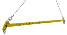
The Lifting Beam:
A lifting beam is a below the hook lifting device that performs the same function as a spreader. It consists of a body and a set of lugs just like a spreader bar but lifting beams generally have one lug on the top in the center and 2 or more lugs along the bottom. The top center lug hooks directly to the crane with no need for upper rigging and the bottom lugs are used to connect to the load in a variety of methods.

The main difference between the two comes down to the engineering. A spreader bar has a very elegant mathematical solution that eliminates opposing loads causing it to act like a pure column. This effect makes spreader bars very efficient at transferring loads and have a much higher capacity then lifting beams for their given size. The downside of spreader bars is that they require upper rigging. This upper rigging comes at a cost for the equipment but also requires a lot more hook height on a crane to lift a given load.
The second difference is that spreader bars can easily made to be telescopic. By constructing the spreader bar using hollow structural steel material you can get two or more pieces to slide inside each other. This allows spreader bars to become 2-3 times larger than the collapsed length allowing the user to have a much more versatile lifting device. In the mobile crane world this distinction is really important as carrying rigging out to site can be expensive and constrained by what they can fit on the crane or truck.
A lifting beam is used when hook height and clearance are important. This is because there is no top rigging and connecting your crane directly to the beam via the top lug eliminates the wasted height that the rigging takes up. This allows you to lift your load a lot higher on a given crane using a lifting beam. However, because the transverse loads are not balancing through the top rigging like on a spreader bar you end up with a bending moment going through the bar. Building the beam strong enough to cope with this bending moment means lifting beams are heavier than spreader bars for an equivalent spread and capacity. The length of of the beam plays a huge roll in this calculation and the difference is sizes becomes increasingly more apparent as the spread increases. So when would you want to use a lifting beam? Lifting beams are commonly used for indoor shop cranes. When your hook height is limited as much as indoor cranes and you don’t need to transport the beam to the worksite every day it makes sense to use a lifting beam not a spreader bar.
Manufacturing
A bit needs to be said about building telescopic spreader bars vs lifting beams since each comes with its own challenges. Spreader bars will require pins, holes drilled in long tubing and a tubing selection that can slide in each other (Stocking Spreader Bar Material). All of these process require a special machine or technique to manufacture. Lifting beams on the other hand are heavier but simpler requiring at minimum an I-beam which can be purchased along with a couple lugs welded on it. Lifting beams give you the flexibility to get creative with the design a bit more than spreader bars. A personal favorite of mine is to make lifting beams out of two formed channels that bolt together. This requires a machine to cut and bend plate steel but allows you to make the channel any height (for exactly the required strength) and doesn’t require welding.
Spreader Bars
PROS:
- Cheaper per foot and per ton of capacity
- Potentially telescopic for improved reach with smaller footprint
CONS:
- Lots of rigging required
- Lots of headroom required for upper rigging
- more complexity with pins, lugs, tubes etc.
Lifting Beams
PROS:
- Efficient use of crane height because of lack of top rigging
- Simple to build - one structural member and some lugs
- potentially weldless design
CONS:
- Achieving 20ft reach requires 20ft beam (hard to transport)
- Size of beam increases dramatically with size.
- Expensive
I hope this article clears up any confusion about the difference between spreader bars and lifting beams. They are often verbally used interchangeable so it can be confusing realizing there is actually a difference. If you are thinking about building spreader bars or lifting beams I encourage you to have a look at what we offer by downloading this example spreader bar: Free spreader bar drawings
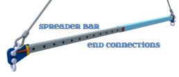
Spreader Bar and Beam End Connection Styles
There are many styles of end connection for spreader bars. In this article I will list a few that I have encountered and give you my thoughts on manufacturing and engineering them. If you are brand new to spreader bars I suggest reading The Anatomy of a Spreader Bar first as it will give you a foundation of terms.
Basic Lug Style:
This is a basic style of end connection. Simple and efficient this is the style of end connection I typically use on smaller lifting equipment where I am focusing on providing the most economic solution. The downside to this system is it can sometimes be hard to get enough clearance around the top hole of the lug while making sure the compression load off this lug is centered in the bar. It also requires the manufacturing of an end cap which is an extra part that could potentially be avoided in other situations. But its simple to build and understand and so it gets used a lot.
Recessed Weld In Lug:
This style of lug that is popular with a few manufacturers I have run into. In this design the end lug is solid, and cut through the tubing and welded in. I feel conflicted about this design. On one hand having the load pass through a solid lug in the end connection is fantastic for engineering however the weld connecting the lug to the tube is prone to cracking. For manufacturing you can potentially get away without using an end cap but unless the shop is specifically set up for cutting slots in tubing this process can be slow and manual.
Advanced Single Lug:
I call this the advanced single lug because it address the major engineering concern of the previous two lugs. With the Basic lug style 1 & 2 the sum of the loads is not centered on the neutral axis of the spreader bar because the top lug is offset from the center of the tubing. This creates an eccentric load, basically a bending moment in your beam and is why you sometimes see smaller/cheaper beams bow over time. This lug design brings the center of the top hole on the outside lugs back inline with neutral axis of the spreader bar and has a large cut away to make room for the rigging. This eliminates any eccentric loading and is maybe more complex looking but simplifies the engineering.
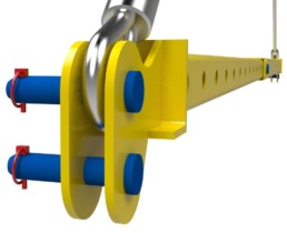
Double Lug:
With this design you have double lug on the end with one or two longer pins where the rigging is attached directly to the pin. This is a less common design because it forces you to use specific style of rigging. The advantages of building bars this way is that you can eliminate the need for shackles and therefor reduce your rigging cost. The manufacturing of this bar is higher then other styles because you are paying for two heavy lugs and two pins. The pins also end up needing to be fairly large as they span the distance between the two lugs. However it is pretty user friendly can adapt to wider slings that shackles might not handle very well and overall eliminates a few rigging components. There are variants of this that include pick points on the outside of the lugs as well
Pivoting End Lug:
This end connection is what I would describe as a premium end lug. With this design you have two lugs, a pin and a third lug that pivots around the pin. Probably the most expensive way of handling the end lug connection this is by far the best for engineering since you eliminate a few eccentric loading scenario by having a pinned connection that balances the load. It also gives you a lot of clearance for rigging and a bit of forgiveness because of the flexibility of the one lug. I like to use this style on larger spreader bars in the 50+ ton range because I feel it is best suited to larger load applications. With heavier and longer bars the additional cost of the more complicated end connection isn’t as substantial when compared to the over all material cost on larger equipment.

End Cap or Build It Yourself Systems:
This style of end camp involves an engineered end cap that slides into the end of either round or square tubing. The idea with this system is that you buy one end from a supplier then as the customer buy and supply the tubing between the end cap as needed. Some systems have bolt in sections to make it semi-adjustable. This design isn’t very common in Canada and seems to be used a lot more on larger sized equipment.
I hope you enjoyed this brief description of different end connections on spreader bars. For smaller bars I typically use the first example and for the heavy weight bars I opt for the pivoting end connection style. If I missed one of your favorites let me know in the comments. If you are thinking about building spreader bar I encourage you to have a look at what we offer by downloading this example spreader bar: Free spreader bar drawings
We are currently building a e-commerce store to sell spreader bar drawings. If that is something that interests you reach out to us and let us know.
Two Pins or Not Two Pins?
Two Pin or Not Two Pin:
The lynch pin of many spreader bar designs is the pin size, or more specifically balancing the thickness of the tube with the diameter of the hole on the inside tube of a telescopic spreader bar. This is always the first calculation I do when I start designing a spreader bar because it is the feature that seems to have the most limitation and sets the course of the design. There is always an internal battle of how to make this more efficient. Bigger holes and subsequently bigger pins allow for higher capacity but are also more expensive and difficult to deal with. So is the question is: Is there a benefit of having two smaller pins verses one large one.
Background on hole failure theory.
There are three basic failure modes for a pin in a hole as show below. Failure mode 1 & 2 are from tearing away the material around the hole mode 3 is elongating the hole and the last would be pin failure. A telescopic spreader bar has a huge amount of material around the hole because of the nature of a hole in a tube so failure mode 1 and 2 don’t really occur. The real failure mode we need to look at is failure mode 3 which is where the bearing load applied to the wall of the lug (or tube) causes the hole to elongate.
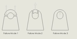
Failure mode 3 is important to us because we need to maintain the correct amount of surface area of engagement between the pins and the wall of the lug. If we allow the holes to elongate too much it could cause localized yielding until a catastrophic failure occurs.
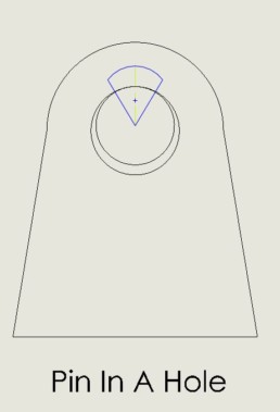
Pin Clearance Vs Hole Engagement:
If you can imagine a pin in a hole where the pin is slightly undersized to allow clearance the actual surface area of engagement between the pin and the wall of the lug is dramatically less than you might think. As the system is loaded the steel will flex and overall engagement will go up but the designer needs to balance the need for clearance around the pin so it can be put in and taken out easily with having the correct amount of engagement in order to distribute the stress properly. This is a fairly well studied problem with lots of engineering to back up the industry practices.
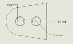
The importance of this back ground is that with two pins you potentially have this problem compounded across each one. In theory if all the clearances and tolerances worked out in worst case it could be possible to get yourself into a situation where one pin was carrying all the load and the other wasn’t loaded. This depends on a lot of factors and is something I will go into further depth in a future article but for now lets just be aware of this potential problem with running two pins.
So Why Use Two Pins:
- Increase load capacity if pin material grade or size is limiting factor
- Increase load capacity if bearing surface of inside tube is limiting factor
- stock fewer sizes of pins
- work around if manufacturing process or available machines are limiting available pin sizes
- Use two smaller pins instead of one large pin if the size of the pin is prohibitively big for user.
What is the effect on cost?
So obviously with a two pin system you will need to supply a second pin and cut an extra holes. If we take equivalent strength pins based on simple shear failure mechanism we find that two 1” pins are approximately the same strength as a single 1.5” pin. Based on some recent high tensile pins that I got custom made in quantities of one I paid 17% more for the 1.5” pin over the 1” so using two 1” pins would be 80% more expensive or about a cost of $100. Keeping in mind this is in my geographical region. In my experience if you can source the pins from a volume supplier where they produce the product at a rate where the labor per pin is almost negligible it becomes more expensive to run 1 large pin then 2. However, having said that, I think the lower production companies can benefit from the flexibility offered from using two pins or one as needed to stock fewer pins. In other words, rather than trying to build and stock 1”, 1.25” and 1.5” pins you can just stock 1” and use two of them in the higher load situations. Potentially saving money by reducing the overhead related to keeping the extra parts being in inventory.
Conversely, you can use the idea of using two pins to reduce the required tubing size rather than trying to save money on the pin itself. Typically, the wall thickness off the tube around the load caused by the pin is more of a limiting factor than the buckling factor of the tube itself so you could add an extra pin and reduce the tubing thickness in order to save you total steel weight. For instance decreasing a 4x4x0.25 tube to 4x4x0.19 saves you 2.75 lbs/ft. This cost saving may offset the increased cost from having two pins. This needs to be checked on a case by case basis and again I think the real savings comes from the flexibility of using it in order not have to stock multiple sizes of material.
So in conclusion depending on the situation you can use two pins. I rarely utilize this option because I generally just opt for a larger pin but have a look at what situation works best for your company. If you would like to read about how using two pins can affect stocking material for spreader bars read: Stocking Spreader Bar Material

Benefits of using an Engineering in Design
Benefits of Using An Engineer In Design & Product Development
When you’re designing a product, you might wonder if the additional expense of hiring an engineer to review or develop your product is worth the cost that the engineering would incur. Depending on the product, or the intended use of the product, it can be very beneficial. Following are some key services that engineering can provide.
Structural Review
Design Engineers are trained to look at the big picture of a product and assess the design for form and function to ensure that the product will perform its intended purpose. They know what to look for and how to find answers to many of questions related to design and product development. One of the most important roles that engineers play, particularly in large structural products but also in the smaller and simpler products, is structural review. Structural review involves determining if the strength of the design is going to be acceptable for the intended use of the product. Engineers can determine the loads that are applied to a product and evaluate the product structure to see if the design can support the intended loads. Experienced engineers might even come up with potential load scenarios that an in-experienced person might not even think to consider.
Material Selection
The materials used in the structure of a product are directly related to the strength of the product, and will determine how well the product will hold up in operation. The geometry or shape of the structure must be developed in conjunction with the material used in the product design, to be certain the product will perform as required.
Some products require high-strength materials to keep the strength-to-weight ratio at an acceptable level. Other products might require materials which are more suitable for handling vibrational loads, low-temperatures, high-pressure, or operating in abrasive environments. Whatever the operational scenarios are, an experienced Design Engineer knows what material properties must be considered, and how to select the most appropriate material for the job.
Manufacturability
Experienced Design Engineers are familiar with manufacturing processes and the limitations of those processes. As a result, for those who not familiar with manufacturing and the processes required to generate manufactured products, it can be beneficial to utilize the experience and knowledge of an engineer to develop your product, so it can be manufactured efficiently. An engineer can provide expertise in developing the product, balancing cost, manufacturability and overall design efficiency which can ultimately help to result in lower overall manufacturing costs for a more efficiently designed product.
Codes, Standards and Regulations
Many products have certain requirements related to design, operation or performance that must be met to ensure the product operates in a predictable and safe way. These codes, standards and regulations often define how the relevant products are to be designed and manufactured, inspected, and the quality control requirements related to the development and manufacture of the product. An experienced Design Engineer knows where to look for applicable regulations. They also have experience in interpreting these standards which can sometimes be very complicated to interpret and apply to the design of the product.
Reduced Liability and Peace of Mind
Another significant benefit of utilizing engineering in the development of your products is that an engineer can provide assurance that your product will meet the requirements of what its intended to do. If you are looking to bring a product to market where if the product could fail and cause significant loss, insurance providers may require that the product be approved by an engineer. But even if engineering isn’t required, it can still provide peace of mind with the design in knowing that it has been reviewed by a qualified third party. And if the product does happen to encounter problems in the future, the engineering will be available to back-up the design.
If you have an idea for a product, or you already have a product that you would like to have developed or reviewed by an engineer, connect with us using the link below and find out how we can assist you in bringing your product to market.
Anatomy Of A Spreader Bar
As an engineer who operates in a number of different industries one of our biggest struggles is to get up to speed on the industry specific terminology and learning the field names of equipment and processes. Lifting equipment also suffers from this as we also have a specific way of referring to different parts of a spreader bar that has been developed over the years. I thought it would be a good idea to share the lingo with the readers in case there is ever a situation where a term is used that isn’t understood. Hopefully this will stop the need for clarifying the lingo in further articles as well.
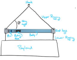
Upper Rigging
The upper rigging is a generic term used for all lifting equipment that is above the spreader bar but below the crane hook. This includes the shackles, cables or chains, master-link if there is one etc. Some spreader bar manufacturing companies sell the spreader bar with the upper rigging included because it is usually specifically sized to maintain a load rating. For instance the loading on the spreader bar changes a lot depending on length of rigging because it can change the sling angle and it can be tricky to get the right capacity on the upper rigging because the required trigonometry to figure out the load. However, if you have or want to source the upper rigging you should be able to source a local rigging supply company for manufactured slings and some of the components such as the shackles will come from one of the big equipment manufacturers such as Crosby.
Lower Rigging
The lower rigging is any rigging or equipment that gets attached below the spreader bar. This can include a wider variety of equipment than the upper rigging as there are many widgets that can be used to help connect the spreader bar to the payload. The lower rigging is usually handled by the end user not the spreader bar manufacture unless there is a scenario where specific rigging is required. The sum of the load on either side of the lower rigging should be vertical or near vertical so specifying the lower rigging tends to be a lot easier to figure out and more situational.
Sling Angle
This is the angle between the spreader bar and one leg of the upper rigging. This is a very important parameter because as the sling angle gets smaller the loads in the spreader bar and rigging increase. The sling angle or at least a range of sling angles are generally specified by the manufacture or engineer and shouldn’t be changed. It is most common to see 45 degrees or 60 degree sling angles.
Rating Plate
According to ASME B30.20 each spreader bar needs to have a permanent rating plate on it. These rating plates should show who manufactured the bar, the capacity, the design category, service class and a few other things. This is one of the most commonly forgotten items that we run into in the spreader bar world. Rating plates are often skipped by do it your-selfers as they can be hard to manufacture without some specific and expensive equipment.
Pin
On the telescopic variety of spreader bar there will be a pin that is used to set the length of the beam and is a pretty straight forward piece of equipment. It is generally the first thing on a spreader bar that gets lost or damaged. Always check required material before replacing one as it is generally made from higher quality steel.
Labels
Each spreader bar should have a set of labels and decals to show capacity and some safety warnings. There are parameters regarding what these should say in B30.20.
Payload
I decided for the sake of clarity in my writing to call the object being lifted as the payload. I would say this isn’t typical industry terminology but when you are talking about engineering “loads” and payloads in the same sentence it helps differentiate the two.
Thanks for reading this article and hopefully we are all on the same page with how to talk about spreader bars now. I will probably update this document every time a new term comes up but for now it is what it is. If you enjoyed the article and want to receive more update from us please take a moment to sign up for our mailing list. If you are just starting your journey into manufacturing spreader bars you should read this article next: An Introduction to Stocking Materials for Spreader Bars.