
There are many styles of end connection for spreader bars. In this article I will list a few that I have encountered and give you my thoughts on manufacturing and engineering them. If you are brand new to spreader bars I suggest reading The Anatomy of a Spreader Bar first as it will give you a foundation of terms.
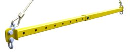
Basic Lug Style:
This is a basic style of end connection. Simple and efficient this is the style of end connection I typically use on smaller lifting equipment where I am focusing on providing the most economic solution. The downside to this system is it can sometimes be hard to get enough clearance around the top hole of the lug while making sure the compression load off this lug is centered in the bar. It also requires the manufacturing of an end cap which is an extra part that could potentially be avoided in other situations. But its simple to build and understand and so it gets used a lot.
Recessed Weld In Lug:
This style of lug that is popular with a few manufacturers I have run into. In this design the end lug is solid, and cut through the tubing and welded in. I feel conflicted about this design. On one hand having the load pass through a solid lug in the end connection is fantastic for engineering however the weld connecting the lug to the tube is prone to cracking. For manufacturing you can potentially get away without using an end cap but unless the shop is specifically set up for cutting slots in tubing this process can be slow and manual.
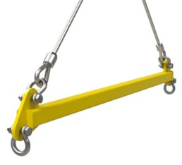
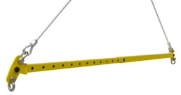
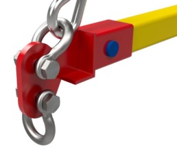
Advanced Single Lug:
I call this the advanced single lug because it address the major engineering concern of the previous two lugs. With the Basic lug style 1 & 2 the sum of the loads is not centered on the neutral axis of the spreader bar because the top lug is offset from the center of the tubing. This creates an eccentric load, basically a bending moment in your beam and is why you sometimes see smaller/cheaper beams bow over time. This lug design brings the center of the top hole on the outside lugs back inline with neutral axis of the spreader bar and has a large cut away to make room for the rigging. This eliminates any eccentric loading and is maybe more complex looking but simplifies the engineering.
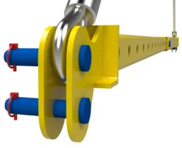
Double Lug:
With this design you have double lug on the end with one or two longer pins where the rigging is attached directly to the pin. This is a less common design because it forces you to use specific style of rigging. The advantages of building bars this way is that you can eliminate the need for shackles and therefor reduce your rigging cost. The manufacturing of this bar is higher then other styles because you are paying for two heavy lugs and two pins. The pins also end up needing to be fairly large as they span the distance between the two lugs. However it is pretty user friendly can adapt to wider slings that shackles might not handle very well and overall eliminates a few rigging components. There are variants of this that include pick points on the outside of the lugs as well
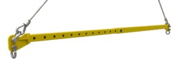
Pivoting End Lug:
This end connection is what I would describe as a premium end lug. With this design you have two lugs, a pin and a third lug that pivots around the pin. Probably the most expensive way of handling the end lug connection this is by far the best for engineering since you eliminate a few eccentric loading scenario by having a pinned connection that balances the load. It also gives you a lot of clearance for rigging and a bit of forgiveness because of the flexibility of the one lug. I like to use this style on larger spreader bars in the 50+ ton range because I feel it is best suited to larger load applications. With heavier and longer bars the additional cost of the more complicated end connection isn’t as substantial when compared to the over all material cost on larger equipment.
End Cap or Build It Yourself Systems:
This style of end camp involves an engineered end cap that slides into the end of either round or square tubing. The idea with this system is that you buy one end from a supplier then as the customer buy and supply the tubing between the end cap as needed. Some systems have bolt in sections to make it semi-adjustable. This design isn’t very common in Canada and seems to be used a lot more on larger sized equipment.
I hope you enjoyed this brief description of different end connections on spreader bars. For smaller bars I typically use the first example and for the heavy weight bars I opt for the pivoting end connection style. If I missed one of your favorites let me know in the comments. If you are thinking about building spreader bar I encourage you to have a look at what we offer by downloading this example spreader bar: Free spreader bar drawings
We are currently building a e-commerce store to sell spreader bar drawings. If that is something that interests you reach out to us and let us know.
Thank for sharing the information most interesting to see what we take for granted where a little bit of design change can improve on the rigging we use.
It was my pleasure Jesse thanks for stoping by and taking the time to read it.