
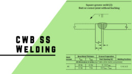
CWB Stainless Welding Procedures
I have been
doing a number of stainless steel welding procedures recently and ran into a
bit of confusion so I thought I would touch on the subject. I hope the
discussion can save other people the time and hassle of figuring some of this out.
It became apparent that I used a lot of short hands for various codes here is a short list:
- CWB - CANADIAN WELDING BUREAU
- CSA W59 - WELDED STEEL CONSTRUCTION
- CSA W47.1 - FUSION WELDING OF STEEL COMPANY CERTIFICATION
- AWS D1.5 - STRUCTURAL WELDING CODE - STAINLESS STEEL
Generally
when you begin to write a weld procedure you start at CSA W59 which is the Canadian
code for Welded steel construction in Canada for the parameters of the weld
then cross reference that to CSA 47.1 (Certification of Companies for Fusion
Welding of Steel) for qualifications of staff and company. However, for stainless
CSA W59 does not touch on the subject at all. It just simply referred people to
the AWS D1.6 code based on the American system. I found this interesting since the
AWS system is good but not the same as the CSA and to have a cross over raised
some questions as to which system had final say and which code covered what. Specifically,
I was look at joint B-P1c which is a partial joint penetration prequalified under
the AWS system but not prequalified in the CSA W59.
AWS D1.6
offers this procedure as prequalified:
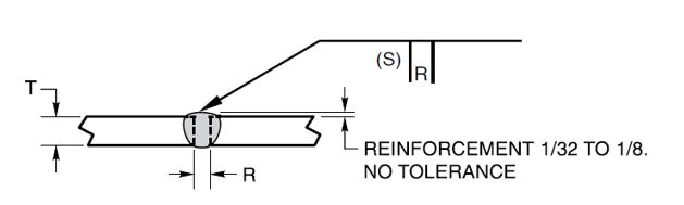
Where as CSA W59 only offers a prequalified weld if its two passes with a ground to sound metal or with a backing strip.

After
chasing that solution for a while it came to my attention that CSA 47.1 had
recently added Annex K that covered stainless steel welding. This section of
the code had recently been adopted by CWB as the approved procedure for qualifying
stainless steel welds/personnel etc. Inside Annex K under clause K.8.3.1 I find
it states:
“Joints that conform with the details specified in Figures 10.1 to 10.14 of CSA W59 and Figure J.8 of this standard, and meet all other requirements of this Annex, shall be designated as prequalified and do not require procedure qualification testing.”
Which loosely translates into
use the prequalified welds in CSA W59 despite it saying in W59 that the code doesn’t
apply to stainless steel welding. As I review the material to write this I also
question what the process would be to qualify a light gauge stainless weld procedure
as Annex K points you to CSA W59 but the prequalified sheet metal procedures
are written out in Annex J of CSA W47.1.
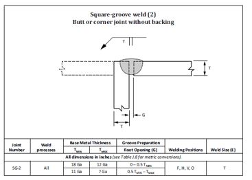
The pre-approved procedure
SG-2 in the sheet steel annex J in W47.1 would have also worked well for what I
was working other than it is for mild steel not stainless.
I work with
these codes every day and I found this cross referencing of codes confusing. I
cant see someone who casually works with these codes successfully navigating
it. On the other hand I feel this expansion of CSA 47.1 is a step in the right direction
in that I believe Canada should have a code/standard for welding stainless
steel. But the approach of cramming the highlights of AWS D1.6 which is 300+ pages
long into annex K is a little strange. It also is weird to refer to CSA 47.1
which is traditionally a qualification code not a design code for design
information. I hope as time progresses this step in the right direction turns
into a Canadian version of the code but for now the additional clarity is
appreciated.
If you found this page trying to find a stainless steel weld procedure. Feel free to email me and lets figure it out. https://basepointengineering.com/contact-simple/
If you are interested in retaining an engineer for the purpose of obtaining your division 2 status with CWB please read: https://basepointengineering.com/retained-welding-engineering/ and give us a call

Reading Spreader Bar Drawings
One of the biggest road blocks to buying things online is the inability to touch, feel and see what you are getting. Basepoint Engineering sells drawings online and we have the same problem. To address this we offer a free downloadable finished drawing pack for everyone to see what our package looks like before they download. You can get this drawing by entering your email below.
But, if you are not used to looking and engineered build drawings every day the drawings themselves can be a bit overwhelming. If you watch the video below it goes through some of the key features and points that you will find in our drawings. This includes:
- Bill of Materials
- Material grades
- Welding specifications
- Balloons
- Assembly drawings vs parts drawing
- Rating plate information
- Welding notes
- Manufacturing notes
- Model Numbers
Enter your Email to Download
Free 5-ton Telescopic spreader bar
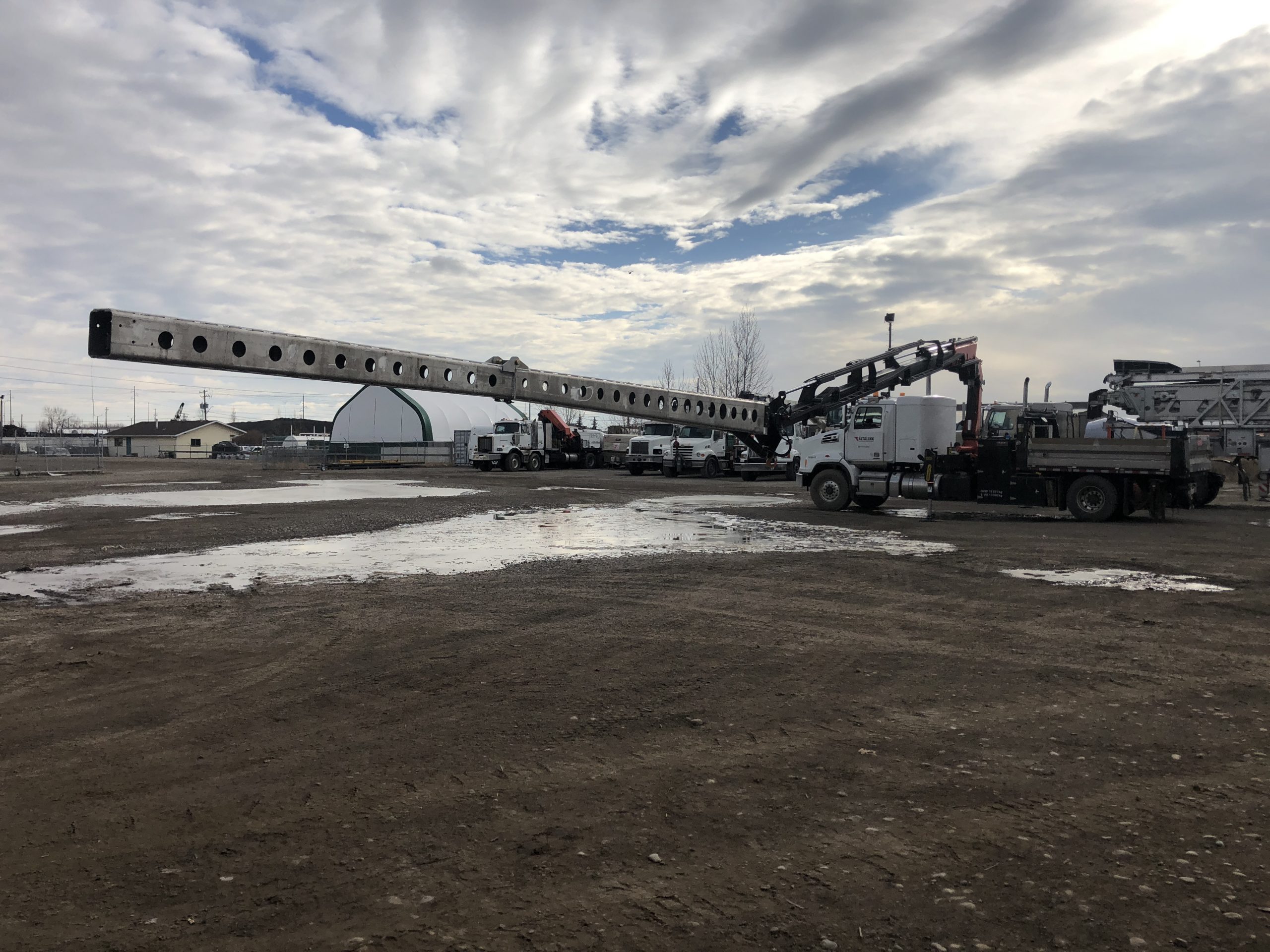
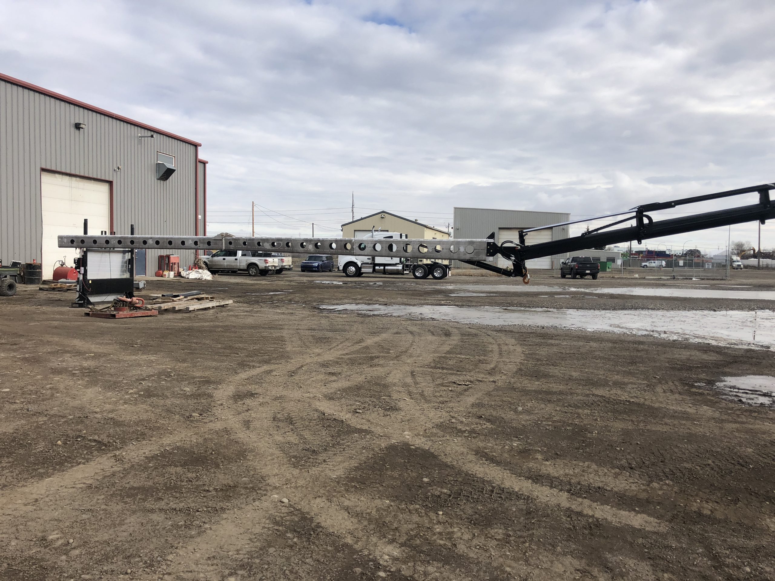
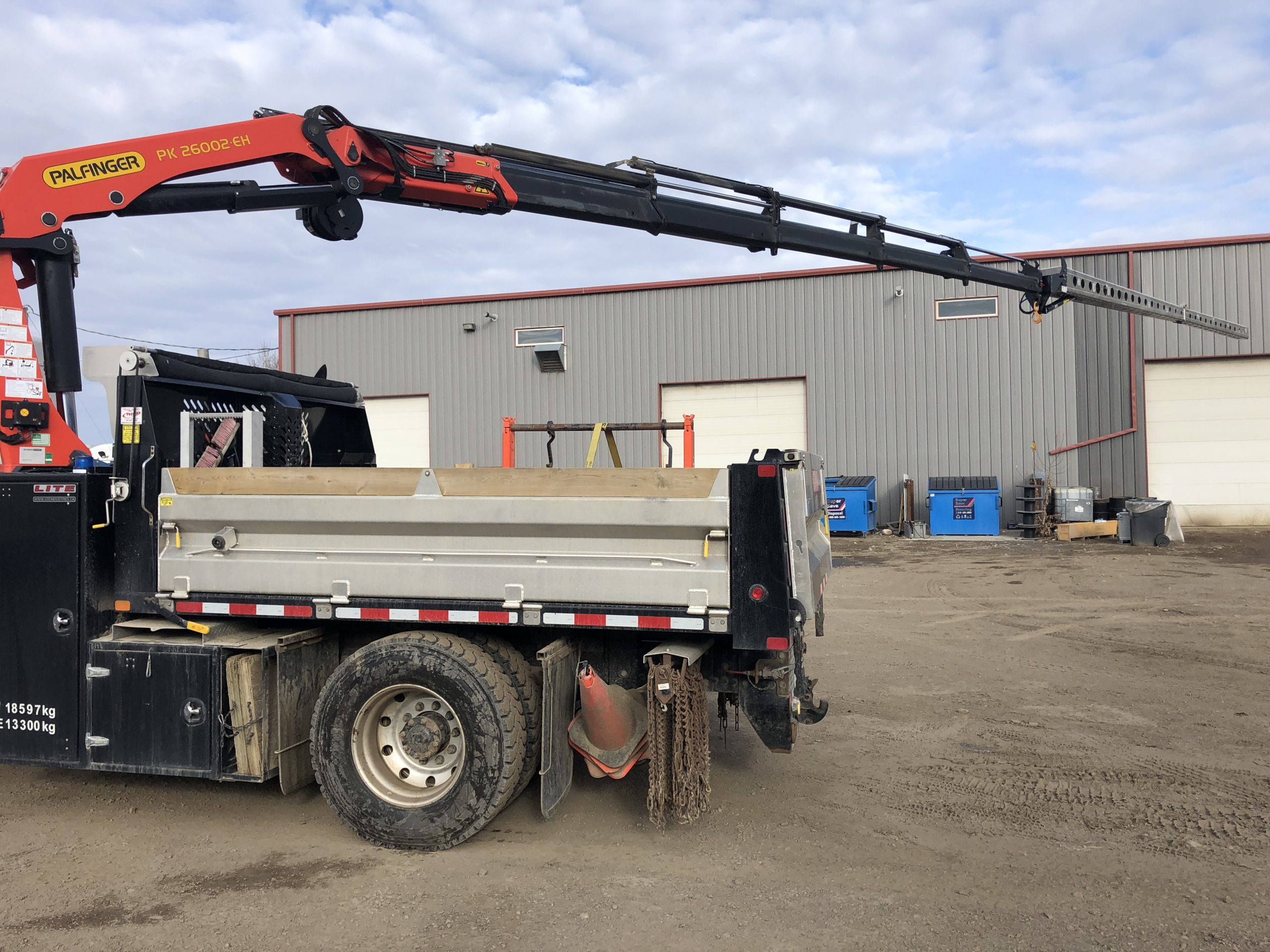
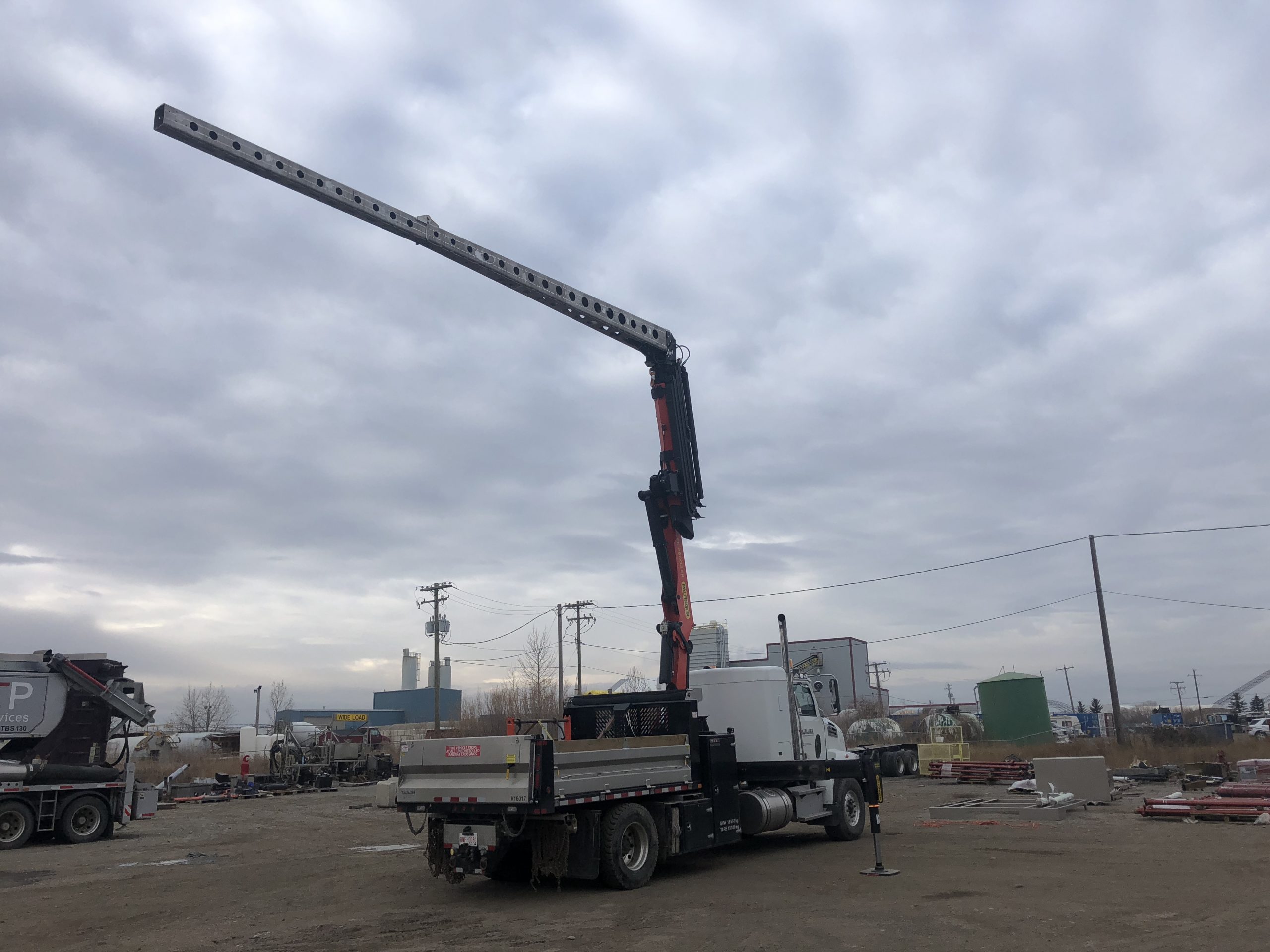
Hydraulic Aluminum Crane Jib
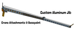
Basepoint Engineering recently had the pleasure of designing this jib for Craneworks Canada. The jib is designed and built for an application in the electricity transmission industry and was custom designed to slide in the end of the specific crane using a quick attach system. The over all length was 30ft and it hydraulically actuated off a remote so that it could be leveled by the operator through out all crane positions. Due to the length and load requirements keeping the dead weight as low as possible was critical so we utilized aluminum construction with lots of weight reducing holes. To help with storage we designed the unit to fold in half and fit in a cradle on the deck.
As part of the service Basepoint engineered the structural components, produced manufacturing drawings with weld specifications, bill of materials and construction information. We then weld inspected and performed a load and stability test to make sure the crane and equipment was stable in the operating range.
Basepoint Engineering works with all sorts of lifting equipment, crane attachments and other mobile equipment. Give us a call for your specific application.
If you enjoyed reading this you might be interested in our reverse jib product line that can be found in our store: Reverse Jib

Custom Crane Block
I recently has the pleasure of building a crane block for a specific custom applications. This is not the first time in my career that I have gotten to design and build a block but is not something many will do often. If you are thinking of building such a device consider reaching out to us. Here are a few take aways I had from the project.
They Are Supposed to Be Heavy:
I can remember one application where we were building a specialized lifting device (not a crane) and it was trailer mounted device to be pulled by a 1-ton truck. For simplicity sake and speed we had a two part line which meant the tension on the cable was high and the cable appropriately thick. In an attempt to reduce the overall weight of the equipment we opted for a light block. This turned out to be a mistake. The block was functionally strong enough to support the load, which I remember being around 5ton, but was not nearly heavy enough to keep the large diameter line taut during unloaded operation. The device was usable but prone to cable winding problems and was certainly difficult to get attached to the load. If you look at modern crane blocks produced by McKissic or other manufacturer they will often have cheek plates added purely to increase the mass of the block. For instance a 5ton McKissic block ranges from 230 to 425lbs in weight. Or if you look at a overhaul/headache ball the reason they have the large round mass above the hook is to keep the line straight. They are meant to be heavy don’t be shy about adding some steel to them.
Think About the Reeving Process:
If you are building a high capacity multi-part block it is imperative that you think about the reeving process. As you can imagine large diameter high tensile cable is hard to bend by hand and threading it around a lot of sheaves can be a painful experience. A bolt together block with lots of opening to work the rope around the sheaves is ideal. A curved plate below the sheave that guides the wire rope around the sheave and back up is also helpful and can be a simple addition. The major manufacturers all have quick reeving systems that aid in the process and this can be a good resource for ideas.
Pullies & Sheaves
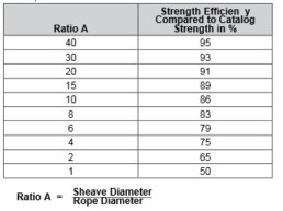
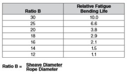
If you are building custom equipment you inevitable have needed to purchase sheaves. From my experience very few suppliers are stocking sheaves in larger sizes and they are usually 12 weeks lead time factory orders. For basic brass bushing solid sheaves you can usually get them designed and made at a local shop for the same money as ordering them from a larger manufacturer and get them weeks quicker. On our last project we were able to source sheaves off the shelf at a crane shop in North America and were able to get them in a week. If you play this game you will inevitable find a sheave close to what you need but not exact. you will try to make the sheaves that you can find work. For instance it will be the wrong diameter, wrong pin size or wrong wire rope size. A good machine shop and an engineer can address the pin and wire rope sizes but if you are thinking of substituting a different sized sheave this reference can be useful. I found this handy Crosby reference (stolen with love: https://www.thecrosbygroup.com/html/en-US/pdf/pgs/380.pdf) outlining the fatigue life and tensile life changes on the rope when none ideal ratios are used. You should probably back this chart up with some sound engineering before you go swapping cables and sheaves around though.
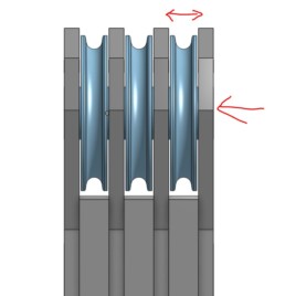
Welding:
If you are building a multi-sheave block and are planning on welding it together pay extra attention to welding parameters and tolerances. With this style of design you will inevitably have a number plates between the sheaves supporting the pin. You will need to apply a lot of heat to get these welded in properly and this heat will cause the steel to move a lot. Maintaining the gap between the plates for the sheaves as well as the hole alignment for the pin us very difficult. While welding you can try and tack the the outer edges of the sheave plates and perform the welding with the pin in it as it helps constrain the movement of the block. However, if you want to avoid spending hours after the fact die grinding holes out and hammering sheaves in make sure you tolerance and gap your parts appropriately.
Some Smaller Things:
Rating Plates: If you read any of my writing you know I am forever reminding everyone to put rating plates on things.
Drainage: Hooks and blocks will inevitably be left outside. Make sure they cant fill up with water and freeze.
Keeper Pins/Bolts: Add a series of bolts or pins around the sheave to make sure the cable cant jump off the sheave.
Make it Grease-able: I like to make the main shaft grease-able but even if you should include some method of greasing it.
Thanks for reading. If you have a custom crane block project on the horizon feel free to give us a call. If you haven’t heard yet we have an online store where you can buy an assortment of lifting equipment drawings that are manufacturing ready. If you have any experiences building crane blocks let me know in the comments.
Lifting Beam Types
There are many different styles of lifting beams out there. Over the years many people have tried to innovate on the simple idea of a beam that spreads the lifting points out from a single crane hook. Here are a few options to think about if you are considering purchasing a lifting beam. Before you start consider doing some background reading on lifting equipment: 10 Things To Consider Before Building Lifting Equipment
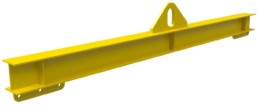
Standard Beam:
This is the most basic option. It has one center pick point that can be used with a shackle or cut into a loop to fit directly onto a crane and has 2 pin on swivel hooks on the ends. A simple and effective version of the lifting beam. These device is usually made from cut and welded I-Beam.

The Bolt Together Version:
Lifting beams lend themselves to a weld free design by utilizing two channels either structural or formed bolted together with the lifting lugs sandwiched in-between. This style is one of my favorites because of the customizable nature, adjustability and lack of welding. In many cases it is easier to cut flat plate and bend it into two channels than buy a specific I-beam size because there is less wasted material from having to buy stock lengths of structural steel.

The H beam:
Im guessing this got its start lifting shipping containers but this style of lifting beam looks a lot like three beams attached together. The idea is that you have a large square four sling lifting system that doesn’t apply sling pressure to what ever it is lifting. I often see this style used with bulk hauling bags or lifting engine/generators skids. I have seen and built many different versions of this bar including under-slung over slung, bolt together, welded etc. The one picture to the right was a special low temperature version we built that had unequal leg lengths and made from formed low temperature rated steel.
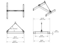
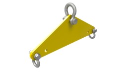
Plate Lifters:
Not to be confused with clamps used for lifting plate steel these lifting beams are smaller in size and usually high capacity lifting beams cut from a single piece of plate steel. Some times they have stiffeners to improve out of plane bending sometimes not. These beams are loved by manufacturers because they only require one cutting process then are ready to work but I find many engineers forgetting to ensure that out of plane bending is addressed.
Adjustable Lifting Beams:
Many different attempts have been made to make an adjustable lifting beam. Some systems have movable lower rigging points. Some just have multiple lugs across the top or bottom. Both systems are trying to give more versatility to the end user. The one shown to the right just has multiple lower holes which I think is the simplest way to get the job done.
Why Choose Basepoint:
If you are considering purchasing a lifting beam take a second to consider buying from us. Tap into our years of experience designing and building lifting equipment. We provide manufacturing drawings on our online store that you can purchase and download today. We can also supply a quote with a finished product as well. If you are thinking about starting but want to chat with someone first you can reach out to us here.
Building OH&S and OSHA Compliant Lifting Equipment
Ready to start building lifting equipment? Give these 10 points some thought! I had written this specifically as a summary to my 10 week course by email about building spreader bars and other lifting equipment but I thought it was too good to keep it locked up for only people that made it through the 10 weeks. I hope you enjoy this breife article and take the time to dive into some of the supporting articles.
Choose a type of lifting equipment:
The first step is to figure out what you need. If you are new to lifting equipment you can consider reading about the anatomy of a spreader bar to bring yourself up to speed on some of the lingo. But the first thing to decide is if you need a spreader bar, lifting beam or something total unique and custom. Review your requirements and address how important the following features are: maximizing head height, cost, load balancing, transport-ability.
Choose a manufacturing style
Now that you know what style of device you need the next step is to chose a style of manufacturing. Is it going to have high tensile steel? or does it need Two pins or one? If you are building a spreader bar you need to choose a style of end connection and whether or not you need spacer plates on the telescopic surfaces. If you are building a lifting beam you need to decide if you want I-beams with lugs welded on it or a weld less system consisting of two channels or even one made of a single heavy plate.
Consider Operating Conditions:
There are three operating conditions that are important to consider before you finish the design of your spreader bar or lifting beam. The first is environmental conditions. Here you should be considering if you are using the lifting device outside where extreme heat or cold could compromise the equipment. Is the beam being used near a smelter giving off heat or out on the ocean where corrosion is a concern. The second condition is how unknown environmental factors, such as wind, load instability, operator set up, will be taken into account. This is important when selecting a design category as the more unknown factors the higher the category and more safety factor is required. The last operating condition looks at the life span of the lifting device and how many cycles it will see during its expected life. If you want to read more how to specify lifting equipment rated for cold temperatures you can read this article: Cold Temperature Rated Lifting Equipment.
Get Engineered Blue Print
You need to comply with the design code of BTH-1. That means your drawings need to be engineered. They also should contain the following: engineering stamp, weight of the device, the rated capacity, manufacturing specifications as well as the design category and service class. If you need engineered drawings you can find them at the Basepoint Store.
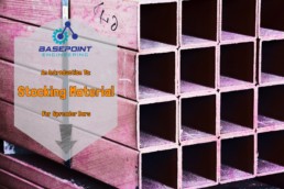
Order/Stock Material:
Have you thought about if it is more efficient to stock material or order on a job by job basis? You might be surprised after reading Stocking Spreader Bar Material that stocking materials for lifting equipment isn’t so bad. While you are thinking about what material to order you need to be prepared to deal with MTRs. A MTR, or material test record is a report that comes with a steel purchase that shows that the material being purchased meets the grade requirements for a specific code. For the structural steels you are probably using to build lifting equipment these will include a minimum yield along with a few other properties. It is highly recommended that you get the MTRs reviewed by a qualified person. As the manufacture the mtrs need to be saved and cataloged by job for future reference.
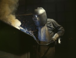
Have a qualified manufacturing process
Each country will have their own structural welding code. ASME B30.20 specifies the use of AWS D14.1 but in Canada we generally specify CSA W59. Both of those codes are full of good information and worth understanding if you are serious about building steel structures. The main concept that manufacturers will need to understand and utilize is the idea of validation and verification as well as the use of pre-qualified weld procedures vs ones that need qualification. AWS D14.1 also has a great section on adjusting your manufacturing procedure based on fatigue limits and matches up really well to the requirements of BTH-1 in relation to total number of cycles.
Make a rating plate
Rating plates are the most common piece to forget. ASME B30.20 requires a that a permanent rating plate is attached to the device listing: weight of the device, manufacturer information, rated capacity and design category and service class. The rating plates are often laser etched or machined and the information should be on the engineered drawing. If you are curious about rating plates check out this article: Rating Plates
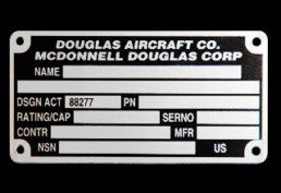
“borrowed from Express: https://www.expresscorp.com/Industrial-Nameplates/Industrial-Nameplates “
7. Post construction testing
B30.20 and BTH-1 states that lifting equipment “should” be tested. Some suppliers in the industry claim to load test every spreader bar some don’t. Some customers specifically require a pull test and others don’t. I often recieve the question about whether you really need to pull test your lifting equipment? Find out by reading about pull testing.
There is an art to building spreader bars and all lifting equipment. Hopefully this gives you the resources you need to be OSHA and OH&S compliant. If you have any questions of comments feel free to reach out.
Jason Thompson

Low Temperature Lifting Equipment
I recently had the opportunity to design a lifting beam that had to be rated to -45 degrees C. Although this might not be super common around the world for equipment designed and used in Canada this pops up occasionally. In this article I will discuss some of the flaws in the low temperature thinking, how we make low temperature rated equipment and why it matters.
The Science Part
So what happens when it gets cold? The molecular structure of various materials can organize themselves in one of two primary crystalline structures called body-centrered cubic (BCC) structures and face centered cubic structures (FCC). I am not going into a lot of detail on this. If you are interested you can read this good summary here: The important thing to know is that most steels are body centric cubic structures and they undergo a transition called the ductile to brittle transition. This transition, abbreviated as DBTT, describes the temperature when a material transitions from behaving ductile and starts to perform in a brittle nature. This means that the static strength of the material might increase but its ability to absorb impact energy is drastically reduced. This poses a critical risk for lifting equipment as it exposes people to a risk of sudden and catastrophic failure when the temperature is low even at a load that the equipment is otherwise rated to operate with.
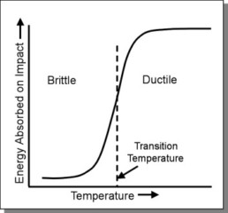
Borrowed without permission from: http://www.materials.unsw.edu.au/tutorials/online-tutorials/2ductile-brittle-transition
Face Centric:
- Aluminum
- Copper
- Lead
- Nickel
- Silver
- Austenitic stainless steels
Body Centric:
- Lithium
- Sodium
- Chromium
- Iron
- Tungsten
- Many common ferrous alloys
What does the code say?
Asme B30.20 & BTH-1 say in clause 1-4.7 that the design provisions in this standard are considered applicable when the temperature is in the range of 25 to 150 degrees F or –5 to 66 degrees C. For equipment operating outside of this range special considerations need to be made. Which is why this article exists. I think people working with low rated equipment need to know some of what goes into getting the temperature rating different than what is said in the code.
Low Temp. Required – What to do
If you absolutely need a low temperature piece of equipment there are a few steps to take. The first and most important to pick a temperature to design to. In my experience the common ones for around here are -20 degrees C or -45 degrees C but this should either come directly from the end user or from published temperature data.
The next step is to find a suitable material to manufacture the equipment out of. This is really where some value can be added to the process. There are a few paths you can take for selecting material. If possible you can select a material that doesn’t go through a brittle transformation such as aluminum. If this fits the project then there are no more issues. More likely you are going to be looking for a steel material that is suitable at your design temperature. Some materials have great low temperature properties and MTRS that include a test performed at a cold temperature. Often you can sift through a few MTRs from your steel supplier and find one that has low temperature impact testing done at the temperature required. I often default to a quenched and tempered steel such as QT-100 in this case which has a service temp of -45 degrees C and other mechanical properties that are great for lifting equipment. The last situation you might get into is that you need a cold temperature rating on a very specific material and you must hire a lab to perform the tests. I was involved in one situation like this with a 4140 shaft that we required to have certain cold temperature performance this process was expensive and time consuming and might not be justifiable on the average project.
The last step of the process is to make sure all of your supporting equipment such as rigging, pins and manufacturing process also meet the cold temperature requirements of the project. Crosby has a line of “cold tuff” shackles that are rated down to -50 degrees F that are relatively affordable but you will have to check the other rigging on a case by case basis.
The Philosophic Problem with Low Temp Lifting Equipment:
I want to share what I feel is the problem when companies request low temperature lifting equipment but do it in a way that doesn’t diminish the risk or sound too controversial. It is important to consider all the risks and build equipment appropriate but what I find is companies will request either a temperature that is arbitrarily low or they haven’t low temperature the whole path of the load.
When a company selects an arbitrarily low working temperature I believe that in most cases it’s a desire to remove all risk of the project without understanding exactly how difficult (or close to impossible) to find material that can perform at super low temperatures such as -50 or -60 degrees C. Unless you are in an extreme situation or in an extreme spot in the world I don’t know too many people or machines that work in -60 degrees C weather and unless the job warrants it the difficulty of finding the correct material could more than triple the cost of the device. I was recently designing a lifting beam that was required to be -45 degree rated but it was a single use device used to install a skid once. -45 degrees isn’t to bad to achieve but on a one use spreader bar could we not just pick a warmer day to install it?
The other situation I see a lot is a company will specify a low temperature lifting equipment without following the whole load path of the lift making sure each piece of equipment is rated to work at a given temperature. My favorite example of this is crane blocks. All the crane blocks I have seen have a -20 degrees or warmer minimum working temperature. I am sure you can buy a crane block that is low temperature rated but does it make sense to hook a -45 degree rated lifting beam onto a -20 degree rating crane block?
I hope you enjoyed this article. If you have any questions or comments feel free to let me know. Keep your eye out to cold temperature rated lifting equipment drawings in the store. If you need help dealing with a low temperature requirement please reach out to me and maybe I can help.
Lifting Beam Case Study 1
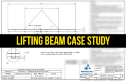
Custom Lifting Beam Case Study
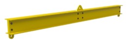
We had the opportunity to design this beam for a customer last week and I thought I would share it with everyone.
Objective: Design a lifting beam capable of lifting long bundles of rebar like material.
Opportunity: Basepoint optimizes the design of all their lifting equipment specifically for the shop that is going to manufacturing them. This beam was construction ready out of either structural channel of formed plate depending on where it ended up and which way was cheaper to produce. The design also had minimal welding which further kept costs down.
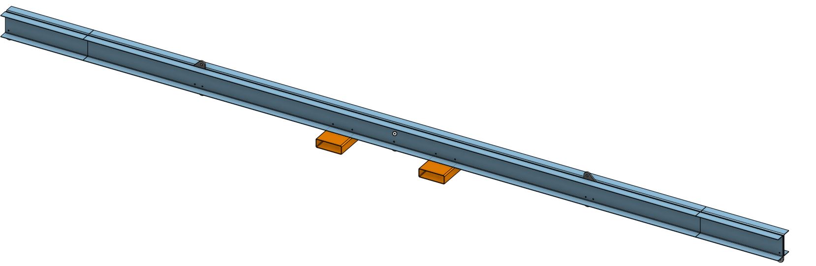
Features:
- Custom built to customer specifications
- Included fork pockets for utilization with a fork lift.
- 5 lower rigging points to support load
- Two upper rigging points
- 5000lb Capacity
- Rigging supplied

Basepoint Engineering is a full service engineering firm who specializes in lifting equipment and mobile equipment. With 10+ years of experience designing and building all sorts of equipment you can lean on our expertise to solve your problems. Tell us about your custom project or have a look at what we are selling in our online store.
Thanks for reading.
Jason Thompson P. Eng.
Do I Need to Pull Test
Pull Testing Lifting Equipment:
I get asked all the time about pull testing lifting equipment. Is it required? How do you do it? Who does it? I have written the answer out via email so many times I thought it was probably time to make a post about it. Lets start with exploring exactly what the code says:
As a note – I highly recommend you purchase ASME B30.20 before working inside this code. I am grabbing snipits from the code so that we can discuss from starting point but you should read and understand the whole code before acting on any of this.
- “New and reinstalled lifting devices shall be tested by a qualified person, or a designated person under the direction of a qualified person, prior to initial use to verify compliance with applicable provisions this volume…”
So we are required to do testing and inspection. It goes on to say:
20-1.3.8.2 Load Test
- “prior to intial use, all new, altered, modified, or repaired lifting devices should be tested and inspected. If performed, tests shall be done under the direction of a qualified person and a written report furnished by such a person…”
- “The load test, if made, shall consist of the following operation as a minimum requirements
- Hoist the test load a sufficient distance to ensure the load is supported by the lifter, or apply the required load if the test is made using a testing machine.
- After the test load is released, visually inspect the lifter for deformation, cracks, or other defects.
The first thing I would look at is just how the words are chosen. There are lots of ifs and should but no musts or shalls. When I read this I feel like it is saying you need to do some sort of testing and inspection and a lift test is recommended but not necessary.
I have seen people interpret this code one of three ways:
- Load test every device produced.
- Do testing but not necessarily load testing.
- Load test each new design as pat of the design validation.
The main issue I have with testing every beam is that in many cases it can be cost prohibitive. For smaller bars, say a 10ft long 5ton there really isn’t a problem as any overhead could pull test it. But take for instance a 100ton lifting beam. To load test this you need a crane, but you don’t want to take that crane to 100% capacity so you end up needing around a 125ton crane. Then you need counter weights – if you are like many companies out there that don’t want 150tons of weights sitting around you end up needing the counter weights off a second large crane. Then you get into the paradox of load testing as there are the same risks for testing the new device as there are for using it. If the equipment breaks there is a chance you could tip the crane over. This process could cost upwards of $10,000 per device.
People often respond to this explanation with why don’t you build a test bed? I don’t think there is much of a savings if you think of the equipment required to test a lifting beam that could be 100ft long and over 100tons capacity. The equipment ends up being heavy and slow to use. The one company around here that has built one it worked really well with lifting beams but it was really awkward to deal with the sling angles on spreader bars. It also had a huge foot print.
But the fact it is hard isn’t a good reason to not be safe.
How Do I Do It?
In Canada we defer to engineers to make decision more often then other places in the world. Here we have a two part process that uses engineering to offset the risk of failure. The first part of the process is to have an engineer design the lifting device. This includes everything in the BTH-1 design code and they certify the drawing. This happens once per design.
The second part of the process is for each individual piece of equipment produced we perform a non-destructive test such as magnetic particle inspection and have an engineer review the equipment and the inspection and issue a certification. This happens when a new piece of equipment gets put into service put also on an annual basis. We generally only do pull testing when the customer or engineer requests it.
This process satisfies our health and safety people and honestly I think there are very few failures.
My thoughts:
I have produced many spreader bars but have only pull tested a few of them. As mentioned above you are testing to either validate the design or to check the manufacturing (or both). I feel a competent engineer following BTH-1 in most cases shouldn’t need to validate the design through pull testing (although they should reserve the right to request it). When I ask for pull testing to validate the design when there are additional unknown parameters, material strength or loading scenario that makes the calculation difficult to estimate. In a straight forward scenario I have found that BTH-1 design code is well written and sufficiently conservative for use with out requiring additional design confirmation. In addition if you are designing to a 3:1 safety factor but only testing 1.25:1 something would have to be drastically off in order for failure to occur.
There are three fundamental things that can go wrong during the manufacturing process of building most lifting equipment: material selection issues, error in the construction procedure (welding problem) or error following the drawings. Load testing addresses most of these issues but does so in a reactive way.
You can also hedge against these problems with a post construction weld inspection to make sure construction matches the drawings and the welding was performed to standard. Material selection can be verified by conducting a review of the MTRS.
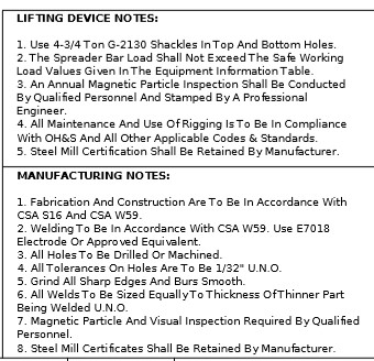
So what is the answer? You must inspect and test, you should load test and who ever is doing the engineering should specify the rest of the process. These are the notes we put on our drawings:
So those are my thoughts on load testing lifting equipment. If any one from the load testing camp wants to let us know how they do it I would love to hear it.
Until next time thanks for reading.
Rating Plates
Spreader Bar Rating Plates
Part of being OH&S or OSHA compliant is having a rating plate on your lifting equipment. This is often a forget part when quoting or building spreader bars and can be difficult for some shops to execute on. Building rating plates takes a slightly different skill set and different machines then it takes to build the equipment themselves.
Lets see what the code actually says:
- Rated load
- Manufactures name and address
- Serial number
- Lifter weight, if over 100lbs (45kg)
- Cold current amps when applicable
- Rated voltage/amps when applicable
- ASME BTH-1 Design category
- ASME BTH-1 Service Class
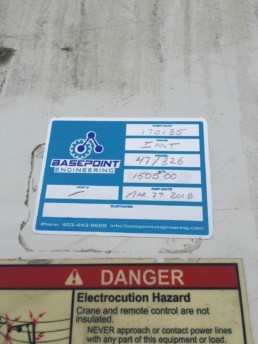
If you buy lifting equipment drawings off us at the Basepoint Store information will generally come in the form of a table on the cover page of the drawings here is an example:
It is common to have some confusion over who the manufacturer is. This can be especially true if a retail rigging shop is getting the bar built at a local manufacturer- who’s name goes on the bar? I usually allow a lot of flexibility on this front and list the manufacturer as the company that wants to keep all the information on file and answer the phone call if there is questions or problem. In the past when I manufactured bars at the wholesale level and I would list my company as the manufacture but brand the rest of the bar for the customer (paint color decals etc) and no one would ever ignore the branding and look at the rating plate and then phone us so I wouldn’t be too concerned about loosing business because of the name in this spot.
For serial number it is really up to the manufacturer to decide but I often use the model number and append it with the sequential number of the unit being produced. So, in the example above it would be 10FE05-04-06-001. What ever the system you decide you need to track the serial number on a unit by unit basis so some system needs to be in place.
Making Rating Plates:
Over the years I have used a few different techniques for manufacturing rating plates. By far the best looking rating plate was an anodized aluminum name plate. You can order these online or locally. They take a laser engraver/etcher to produce which you can spend a lot of money on if you want to build them yourself. To make these work we would weld a ¼” plate roughly the same size as the rating plate with 4 tapped holes in it on the lifting beam so these could be bolted on after. Riveting can also work well especially if it’s a blind one sided rivet but be sure the engineer is okay with your drilling holes into a structural member before you do this. In my experience you are paying $15-$60 per rating plate depending on quantity and how fast you need it.
We also produced many rating plates using a CNC milling machine or with hammer and punch sets. We did this before we got serious about producing lifting equipment. We had the manufacturing tools and some spare steel so it wasn’t such a big deal to machine a rating plate. The finished product doesn’t look nearly as sharp as the weight of machined letters tends to be large and takes a lot of space to get the information on it. This is also a expensive way for most people to make rating plates because you are paying for an expensive machine and programming to make each rating plate. I have paid up to $100 per rating plate for this style.
Lastly, I have never tried this but I think a semi-permanent aluminum foil sticker could also be sufficient for rating plates. For structural inspections we adhere a special aluminum foil sticker to the equipment we inspect and then write the details with a ball point pen on the sticker. These stickers have no problem lasting the year between inspections and depending on wear can last many years. If you can re-adhere the sticker on request or during the annual inspection I think this is a solution that could happen for less than $1. I might put these on our online store but in the meantime you can get something similar from http://www.screencraft.ca/
Above and beyond the rating plate ASME B30.20 also requires warning lables. This is what the code says: “Where the size and shape of the lifter allow, all lifters shall have labels, affixed to them in a readable position, that include appropriate single word, according to ANSI A535.4 that include cautionary language to provide danger warning or caution to operators and others against:
- Exceeding the rated load, or lifting loads not specified in the instruction manual
- Operating a damaged or malfunctioning unit
- Lifting people
- Lifting suspended loads over people
- Leaving loads unattended
- Removing or obscuring warning labels
- Operating without having read and understood the operating manual
- Not staying clear of the suspended load
- Lifting loads higher than necessary
- Making alterations or modifications to lifters
Hopefully that gets you thinking about rating plates and maybe there will be less chance that the rating plate gets forgotten on future builds. Thanks for taking the time to read this article. If you are hungry for more content you can read a bit about the service class and design catagories at this article ASME B30.20 & BTH1: intro to below the hook design